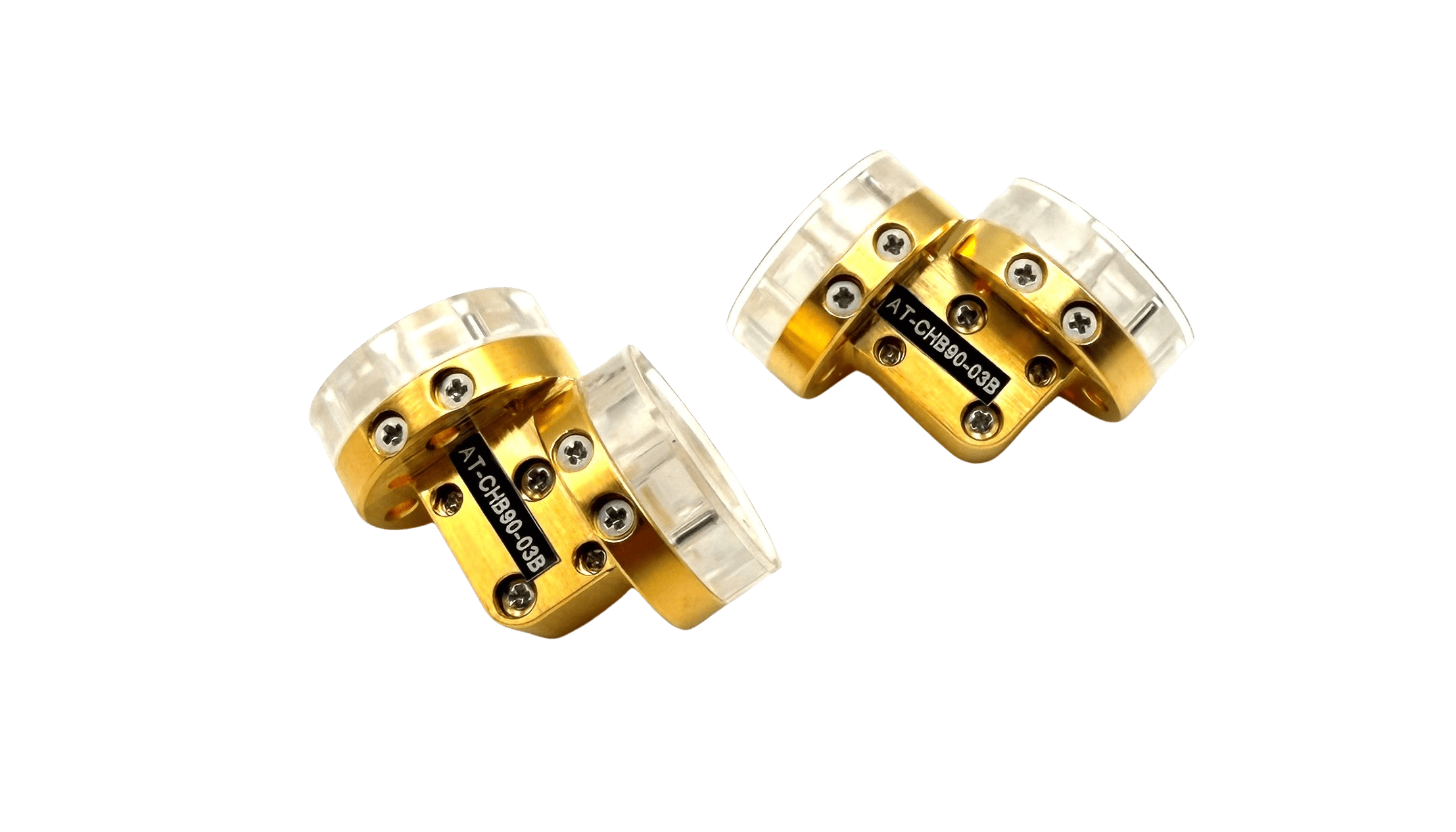
Waveguide Bends from 40 GHz to 1700 GHz
AT Microwave's waveguide bend portfolio delivers precision signal routing solutions spanning from WR19 (40-60 GHz) through WR0.65 (1100-1700 GHz). These passive components enable system designers to construct compact, efficient signal paths while maintaining low insertion loss and excellent VSWR performance across the entire frequency range. Available in both E-plane and H-plane configurations with multiple bend angles, these components serve applications from laboratory test setups to operational defense and SATCOM deployments.
Technical Specifications
- Frequency Range: WR19 to WR0.65 covering 40 GHz through 1700 GHz
- Waveguide Sizes: Complete coverage including WR19, WR15, WR12, WR10, WR8, WR6, WR5, WR4, WR3, WR2.8, WR2.2, WR1.9, WR1.5, WR1.2, WR1.0, WR0.8, and WR0.65
- Configurations: E-plane and H-plane bend geometries
- Bend Angles: Multiple options including 30°, 45°, 60°, and 90° configurations
- Performance: Optimized for low insertion loss and excellent VSWR characteristics across operating bands
- Materials: Precision-machined aluminum, brass, and copper constructions
- Customization: Non-standard angles, flange types, and surface finishes available
Applications
- Test & Measurement: Integration into laboratory systems and device characterization setups requiring reproducible performance
- Radar Systems: Signal routing in high-frequency radar architectures demanding minimal loss transmission paths
- SATCOM & Space: Compact payload integration for satellite communication and RF system architectures
- THz Research: Support for spectroscopy, imaging, and material analysis applications in sub-THz and THz frequency bands
- 5G/6G Infrastructure: High-frequency signal distribution in next-generation communication system layouts
European customers and integrators can access AT Microwave waveguide components through bq-microwave, supporting both rapid prototyping and production deployments. Contact us for detailed technical specifications and custom quotations.